Useful data? Cooling with filter fans
„2500 cm³ Capacity, trick“…“268 PS, trick“…“275 km/h max. Velocity, trick“, As a kid, these values were powerful arguments to steal the cards from the opponent in an auto quartet. After a few rounds you knew your top cards and always knew exactly which value you had to conjure up for the next trick. In addition to cars, there were also motorbikes, aeroplanes, ships, etc. The information about each engineering masterpiece was diverse and the numbers impressive. Coming of age, you realise that pure numbers are not always what make an impression. Things that have a real impact are much more important: Facts!
It is not only the case for thermal management that there is a flood of information on technical data these days. And sometimes the usefulness of various figures for the customer is more than questionable. One example is the air throughput values of filter fans.
Pfannenberg has the core competence to focus on the relevant facts and thus provide targeted transparent application advice.
Cooling with filter fans.
Filter fans offer a simple and efficient way of cooling. In order to cool down heated electronic parts or components, cold air, usually from the environment, is fed into the control cabinets. The unwanted warm air is thereby blown out of the control cabinet. At the same time, a predefined filter medium permanently prevents the penetration of possible contamination from the ambient air. In order to be able to guarantee this property, there is a decisive value, the IP protection class (Ingress Protection).
For a given supply air temperature, the amount of airflow is the decisive factor influencing the possible cooling capacity. For the heat balance of the application, the calculation is now simple. More cooling requires more air volume. Assuming that the protection classes of the different filter fans are the sa.me, the manufacturer with the largest airflow will score points.
Airflows?
Airflows can be measured in many ways on one and the same product. If you consider the entire filter fan as a unit, consisting of fan, housing and filter, you can specify the free-blowing airflow for this. An air exchange can only take place if the supplied air can also be discharged. To ensure this under the aspect of IP protection, a pairing of filter fan + exhaust filter is used in practice.
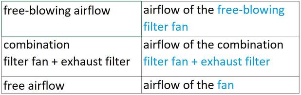
Due to its construction (housing and filter), the exhaust filter represents a resistance to the airflow. The ability of the fan-and-filter unit to actively convey air, combined with the exhaust filter's ability to provide resistance to the airflow, determines the actual possible airflow of this combination and thus the available cooling capacity for the customer. Using several exhaust filters reduces the resistance to the airflow and one thus comes closer and closer to the value of the free-blowing airflow of the filter fan.
- In some data sheets you will find the value free airflow. This is purely a statement by the fan manufacturer for his component. This high value sounds very interesting, but has no significance for the expected cooling performance!
The customer is only given the impression that high-quality components are being used. However, the primary goal should be to combine high-quality components into a product that best suits the customer's needs and application.
A filter fan is a simple but quite pragmatic example. All components must be of high quality, but it is important to determine the best combination that achieves maximum airflow with maximum possible IP protection. The free airflow is not that important here.
The fan - not so simple after all
The airflow of any filter fan is dependent on the resistance it faces. This dependence is shown in a corresponding diagram. The course of the characteristic curve can be recognised as strongly non-linear. However, you can also see in which part of the graph the filter fan has a pressure-stable behaviour and where not.
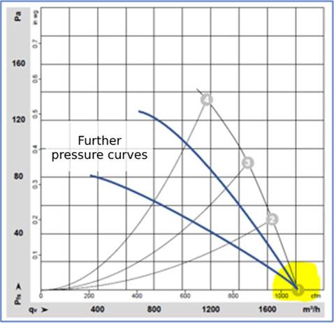
This curve is different for each filter fan and is significantly influenced by the housing design (free air cross-sections, louvre blade design, surface finish, etc.),the selected fan and the filter medium used.
Within the airflow there are also passages in which turbulent flow conditions can influence each other and thus contribute to the complexity of the overall picture.
Taking all these factors into account, protection against environmental influences such as dust, water and oily air must also be ensured. Although the filter medium provides a kind of protective shield, it also reduces the airflow. A well-tuned product therefore requires the optimal interplay between airflow and penetration protection.
The values given by the fan manufacturer are always at a much higher level and represent the theoretically maximum achievable value for a filter fan (100 %). Both filters and the housing are natural resistors and cause the airflow values to be much lower
(usually <50 %).
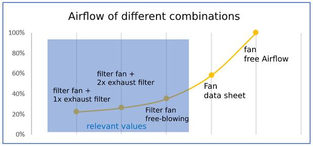
A sobering result, but also a fact independent of the manufacturer. As the saying goes, everyone boils with water.
- It should be noted that for a meaningful calculation of the cooling capacity, only the values from the combination of filter fan + exhaust filter count.
What to do?
Pfannenberg recommends using only the value for free-blowing airflow and the value for filter fan + exhaust filter. This ensures reliable airflows and thus reliable cooling. Detailed information is provided by the pressure diagrams of the complete unit (usually included in the product sheets).
Only these values help our customers to calculate whether their application is sufficiently cooled or not.